How to make your personal USB Mobile Charger.
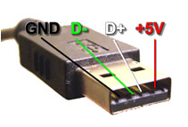
Now the charging of your mobiles has been made easy with the help of USB outlets present in the Laptop and PC. For the charging of your mobile phone, this circuit provides you a regulated voltage of 4.7 volts. 5 volts of DC voltage and 100mA of current is being provided by the USB outlet which is well enough for the mobile phone charging slowly. We can use this circuit to charge the mobile while we are in journey also. So, we may treat it as Mobile Phone Travel The USB port of the mobile is used for the charging, as the USB port is the very helpful voltage source that can charge the mobile. Nowadays, there are two to four USB ports on the laptops that are available in the market. USB actually refers to Universal Serial Bus. It is one of the newest incarnations of method which is used to get information in as well as out from your computer. We are concerned at the fact that ±5 volts of power is being provided by the USB port to the external devices and can avail at the pin number1 while on pin number 4, it is 0V. Till 100 mA of current can get from the USB port which is more than sufficient that we required for this small application.
 The large number of mobile batteries work on 3.6 volts 1000 to 1300mAh.These battery are combinations of three Lithium cells whose voltage rating is 1.2 volts for each. And for charging mobile quickly there is a need of 4.5 volts and current range of 300-500 mA.
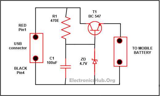
USB Mobile Charger Circuit Diagram:
USB Mobile Charger Circuit Diagram – ElectronicsHub.Org
Components used in this Circuit:
- R1-470E
- C1-100uF/25V
- T1-BC547
- Zener diode-4.7V/. 5W
- Diode-1N4007
- Resistor: Flow of current in the circuit is being controlled by the resistor.
- Capacitor: It is mainly used to store the charges. It is of two types polarized and non-polarized, electrolytic capacitor is an example of polarized while ceramic and paper is non polarized.
- Transistor: It used to enlarge the signal strength or to open or close the circuit.
- Zener Diode: When the voltage achieves the breakdown point it starts working but in the reverse bias state.
- Diode: It is a having two terminal named as anode and cathode. It allows the current to flow only in the forward direction while stopping the flow of current in the backward direction.
USB Mobile Charger Circuit Description:
 The large number of mobile batteries work on 3.6 volts 1000 to 1300mAh.These battery are combinations of three Lithium cells whose voltage rating is 1.2 volts for each. And for charging mobile quickly there is a need of 4.5 volts and current range of 300-500 mA.
If you want to increase the efficiency of your battery than it is good to charge it slowly. The circuit which is explained below work on 4.7 regulated voltage and provide sufficient amount of current for the slow charging of your mobile phones. The voltage at the output is harmonized by the transistor named T1. While the output voltage is being controlled by the Zener diode ZD and the polarity of the output which is supply is protected by D1.
”A type” of USB plug should be connected with the front part of the circuit. To ease the polarity identification connects pin1 to the red color wire while the black color of the wire is connected with pin 4.Now connect the output of the circuit with the appropriate charger pin to attach it with your mobile phones. After all the parts of the circuit gather together, put the USB plug in the socket and from the circuit measure the output with the help of multimeter. If you got the correct output and if the polarity is connected in the right manner then attached your mobile phone with it.
Now a days you will get a multicharger easily available marker just purchase one and charge your moble easily when you are in train or bus as every now carries laptop or note pad with them.
Note: Extreme care is needed to be taken that polarity are connected in the right manner, if it attached in wrong style it will damage the battery of your mobile phone.
For constructing USB mobile charger, there is a need of USB cable and the cable must have minimum one male plug with a strip back of about 5cm having external padding and safeguard from the “uncovered” end of the USB cable. In general the USB cables are made up of four cables of colors red, while along with black and green ( along with the protestors). As the wire of green and white are used to transfer the data, so there is no need of that wire hence these wires can be trimmed (there we should need to pay attention that the wires within their padding and are not exposed). Typically black color wire is negative one while the red color wire is positive one. 5V is the voltage that we get from the USB port. And more than 500mA current cannot be supplied to the device that is attached to the USB port. Attached the power line with the USB plug examine the right polarity.
So thats it. Hope you guys like it. If yes then please .. comment down below and do not forgot to like follow and share our social media platforms.
Facebook Page:- https://www.facebook.com/theprogrammer.harshit/
Facebook Page:- https://www.facebook.com/theprogrammer.harshit/
Instagram:- https://www.instagram.com/computerscience321/
Google Plus:- https://plus.google.com/u/0/communiti…/117296242526461886479
Twitter :- https://twitter.com/cssolutions321
Google Plus:- https://plus.google.com/u/0/communiti…/117296242526461886479
Twitter :- https://twitter.com/cssolutions321


Comments
Post a Comment